A crystal radio is a radio designed for receiving audio (voice) broadcasts, it was invented around the beginning of the 20th century and became extremely popular in the 1920’s and 1930’s, allowing millions of people to access radio broadcasts that otherwise would have been prohibitively expensive, the majority would have been self constructed sets rather than commercial devices, this sparked a huge interest in radio and electronics and ultimately was the catalyst for the rise of commercial radio.
The reduced cost of vacuum tubes and increased reliability led to the downfall of the crystal radio, however it continued to see sporadic usage and has had numerous revivals to the present day, the ease of construction, low cost and no need for a power source means it still sees usage in poor countries and is a popular project for electronics and radio hobbyists.
Crystal radios are primarily designed to receive Amplitude Modulated (AM) broadcasts, although examples have been made that can receive Frequency Modulated (FM) broadcasts, the most common band used is the medium wave broadcast band which roughly spans 530 to 1,700 kHz.
Theory of Operation
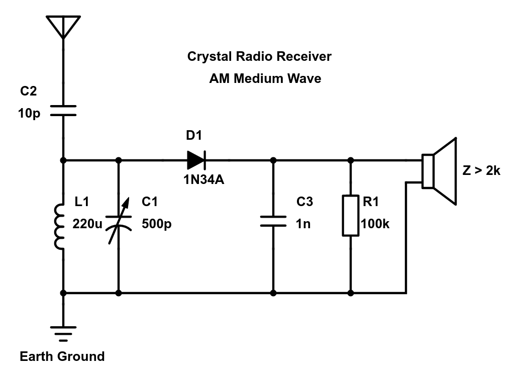
While there are many variations in design all crystal radios consists of four main blocks, the antenna, tuner, detector and speaker.
The antenna is chosen to receive radio waves as efficiently as possible, for medium wave AM band a monopole, loop or ferrite rod antenna is a common choice, there are two options for connecting the antenna to the tuner, magnetic or capacitive coupling, I opted for the latter which is the purpose of C2.
The tuner in the majority of sets consists of a fixed inductor (L1) and a variable tuning capacitor(C1), the tuning capacitor needs a value of at least 500pF to cover the entire medium wave band, for inductance a value between 200uH and 250uH is often used, this forms an LC tank circuit which resonates at a specific frequency, given by the equation:
$$ f_0 = \frac {1}{2\pi\sqrt{LC}} $$
Solving for inductance gives the equation:
$$ L = \frac {1}{4\pi^2Cf^2} $$
It's preferable to use the lowest inductance possible as longer coils tend to have greater resistance which reduces the Q (quality) factor of the coil, however since Q is tied to bandwidth too much can also be an issue.
In my case for the medium wave band I decided on 220uH inductor and a 720pF tuning capacitor I had in my parts bin, you will most likely want to wind your own inductor as commercial inductors of this value normally use ferrite cores which can introduce losses, it may work fine but I haven’t tested it, in any case using an air core coil is traditional.
The detector (D1 & C3) is used for demodulating (extracting) the audio from the RF carrier, back in the day this was an actual lump of crystal such as galena or iron pyrite, the ‘cat’s whisker’ would be adjusted over the surface until a sensitive spot was found, various alternatives have also been used, for simplicity I went with a 1N34A germanium diode (alternative 1N270), the diode choice is very important, germanium starts to conduct as low as 0.1V, I tried a common silicon 1N4148 which gave very poor sensitivity, a schottky diode may be a viable alternative here, the value of the capacitor is not critical, 1nF worked for me.
Finally for the speaker I used a high impedance piezoelectric earpiece, these have an extremely high impedance, so much so that a 100k resistor (R1) is required to provide a suitable discharge path, traditionally a more conventional high impedance speaker would be used giving an impedance around 3k to 10k, these are still available from places like ebay albeit more expensive.
Assembly
For designing the inductor I used the excellent free program Coil32 which I highly recommend you check out, this gave me the number of turns required.
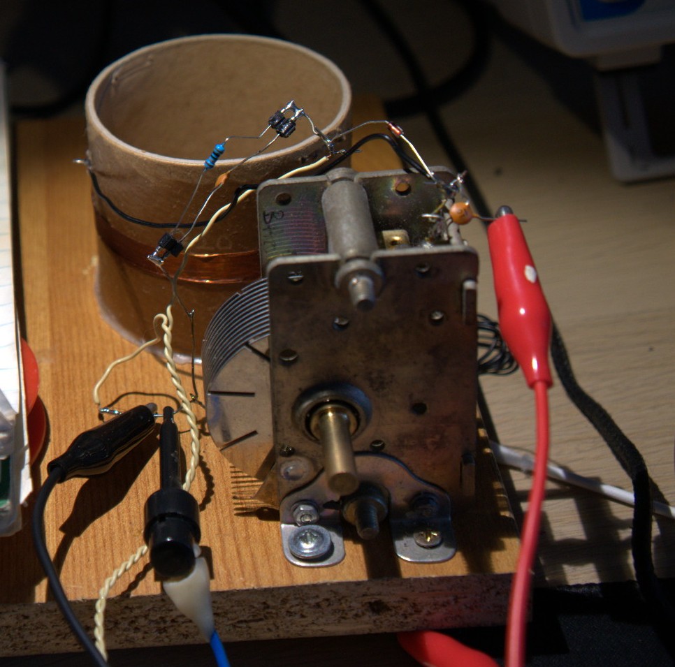
Winding the coil is a bit of an art in itself and can only be learned through experience, I typically use a wax coated cardboard tube, wind the coil as neatly as possible, then coat it with more wax to secure it, this has the advantage over varnish that it sets hard right away, in any case the value is not super critical so there is no need to worry if you do not have an LCR meter handy, go with the calculated number of turns and add a few more for luck.
I mounted the coil and tuning capacitor on a piece of scrap wood, since this is so simple I decided against using a PCB and simply wired it point to point, I made provision for swapping the detector parts using female machine pin headers so I could experiment.
I plan on remaking it much nicer at some point, there is many good examples made by Dave Schmarder.
Testing
Having a strong AM station nearby is pretty much required, you will have trouble receiving weaker stations, although with a good antenna it should be possible, I had no problems receiving a 2kW station located about 3km away even inside the house with a cheap monopole, some European countries no longer broadcast medium wave so you may have more difficulty there.
For a test signal I used my TinySA with 1kHz AM modulation, a signal inserted at -7dBm was clearly audible and was detectable as low as -23dBm, although I noticed a decrease in sensitivity at the low end of the band likely because Q is frequency dependent.
Improvements
The nice thing about crystal radios is there is a lot of things you can do to improve them, such as adding an audio or RF amplifiers, different bands, different detectors, different coil winding methods, audio transformers and so on, so making one is definitely worth the time.